REAR ABS WHEEL-SPEED SENSOR INSPECTION
BHE041543710W02
Installation Visual Inspection
1. Inspect the following items:
-
• If there is any malfunction, replace the applicable part.
-
(1) Excessive looseness or play of the ABS wheel-speed sensor
-
(2) Deformation of the ABS wheel-speed sensor
-
(3) Deformation or damage of the ABS sensor rotor
Clearance Inspection
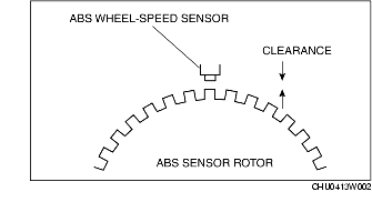
1. Verify the clearance between the ABS sensor rotor and the ABS wheel-speed sensor.
-
• If there is any malfunction, check for improper installation, and replace if necessary.
-
Clearance
-
0.3-1.1 mm {0.012-0.043 in}
Resistance inspection
1. Measure the resistance between the ABS wheel-speed sensor terminals.
-
• If there is any malfunction, replace the ABS wheel-speed sensor.
-
Standard
-
1.3-1.7 kilohms
Voltage Pattern Inspection
1. Lift up the vehicle, and connect an oscilloscope to the ABS wheel-speed sensor connector.
2. While rotating each wheel by hand inspect the voltage pattern.
-
• If there is distortion or noise, inspect the sensor rotor.
Voltage pattern (reference)
-
• Oscilloscope setting:
-
1 V/DIV (Y), 2 ms/DIV (X), AC range
-
• Vehicle condition: Driving 30 km/h (18.6 mph)
-
Note
-
• As the vehicle speed increases, the voltage increases and the wave period shortens.
Sensor Output Value Inspection
1. Turn the ignition switch off.
2. Connect the WDS or equivalent to the DLC-2.
3. Select the following PIDs using the WDS or equivalent:
-
• LR_WSPD
-
(LR wheel-speed sensor)
-
• RR_WSPD
-
(RR wheel-speed sensor)
4. Start the engine and drive the vehicle.
5. Verify that the display of the WDS or equivalent shows the same value as the speedometer.
-
• If there is any malfunction, replace the ABS wheel-speed sensor.
