1. Remove the engine cover. (See ENGINE COVER REMOVAL/INSTALLATION.)
2. Remove the battery cover.
3. Disconnect the negative battery cable.
4. Remove the catalytic converter.
(See EXHAUST SYSTEM REMOVAL/INSTALLATION.)
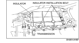
5. Remove the insulator.
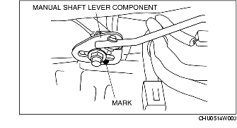
6. Mark the manual shaft lever component as shown in the figure.
7. Separate the manual shaft lever component from selector lever.
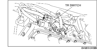
8. Disconnect the TR switch connector.
9. Rotate the manual shaft to the N position.
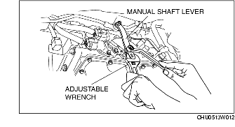
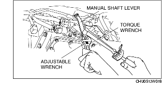
10. Set the adjustable wrench as shown in the figure to hold the manual shaft lever.
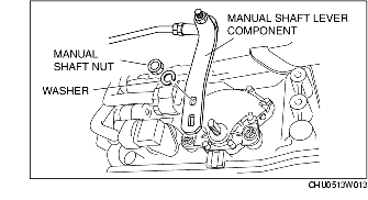
11. Remove the manual shaft nut.
12. Remove the washer and manual shaft lever component.
13. Loosen the TR switch mounting bolts.
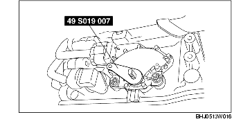
14. Using the SST and by turning the TR switch, adjust the positions of the manual shaft and the TR switch neutral hole.
15. Tighten the TR switch mounting bolts.
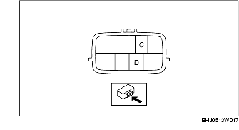
16. Inspect for continuity between TR switch terminals C and D.
17. Remove the SST.
18. Install the manual shaft lever component and washer.
19. Set the adjustable wrench as shown in the figure to hold the manual shaft lever.
20. Tighten the manual shaft nut using a torque wrench.
21. Shift the selector lever to P position.
22. Turn the manual shaft lever to P position.
23. Inspect TR switch continuity. (See Continuity Inspection.)
24. Connect the TR switch connector.
25. Align the mark of the manual shaft lever component as shown in the figure.
26. Install the manual shaft lever component installation nut.
27. Install the insulator.
28. Install the catalytic converter.
(See EXHAUST SYSTEM REMOVAL/INSTALLATION.)
29. Connect the negative battery cable.
30. Install the battery cover.
31. Install the engine cover. (See ENGINE COVER REMOVAL/INSTALLATION.)
32. Inspect TR switch operation. (See Operating inspection.)