TURBINE SENSOR INSPECTION
BHE051319200W06
-
Caution
-
• Water or foreign material entering the connector can cause poor connections or corrosion. Be sure that water or foreign material do not enter the connector when disconnecting it.
Visual Inspection
1. Remove the turbine sensor. (See TURBINE SENSOR REMOVAL/INSTALLATION.)
2. Make sure that the turbine sensor is free of any metal shavings or particles.
-
• If there is any malfunction, clean them off.
3. Install the turbine sensor. (See TURBINE SENSOR REMOVAL/INSTALLATION.)
Element inspection
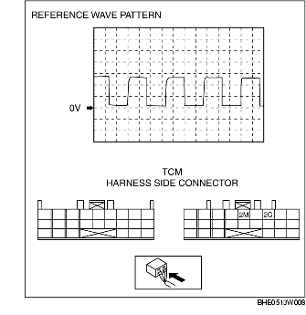
1. Verify using an oscilloscope that the wave pattern for the turbine sensor signal that is input to TCM terminal 2G is the same as the reference wave pattern.
-
• If the actual pattern of the turbine sensor signal is not the same as the reference pattern, inspect and repair the following items:
|
Wave pattern
|
Malfunction cause
|
|
No wave pattern (fixed at HI)
|
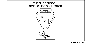
• Open circuit between turbine sensor terminal (A)-TCM terminal 2G
• Open/Short circuit between turbine sensor terminal (B)-battery
|
|
No wave pattern (fixed at LO)
|
• Short circuit between turbine sensor terminal (A)-TCM terminal 2G
|
|
Wave pattern HI is too low
|
• Harness malfunction between turbine sensor terminal (A)-TCM terminal 2G
• Insufficient output from the turbine sensor
|
|
Wave pattern LO is too high
|
• Poor connection (loose GND) between turbine sensor terminal (C)-TCM terminal 2G
|
|
Wave pattern too wide/narrow
|
• Metal shavings (foreign material) on turbine sensor
• Reverse and high clutch drum rotation fluctuation
|
-
• Connected terminals: 2G (+) and 2M (-)
-
• Equipment setting: 5V/DIV (Y): 250 microseconds/DIV (X)
-
• Measuring conditions: M range, 1st gear at 20 km/h {12 mph}
2. Verify the wave pattern of the turbine sensor signal again, and if the malfunction is not resolved, replace turbine sensor.