1. Remove in the order indicated in the table.
2. Install in the reverse order of removal.
3. Inspect the rear wheel alignment.
(See REAR WHEEL ALIGNMENT.)
|
1
|
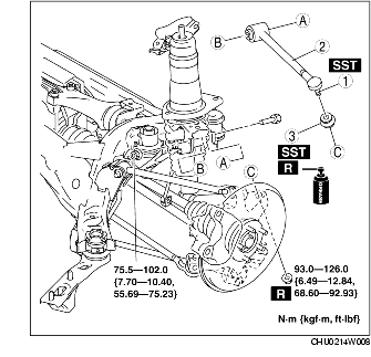
Rear lateral link (upper) ball joint
|
|
2
|
Rear lateral link (upper)
|
|
3
|
Dust boot
(See Dust Boot Installation Note.)
|
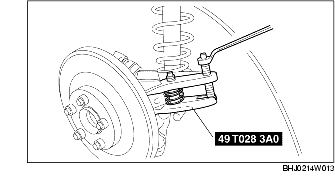
1. Using the SST, disconnect the rear lateral link (upper) ball joint.
1. Wipe the grease off the ball joint stud.
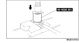
2. Fill the inside of the new dust boot with grease.
3. Using the SST, install the dust boot to the ball joint.
4. Wipe off the excess grease.