1. Perform DSC configuration. (See DSC CONFIGURATION.)
2. Remove the front suspension tower bar. (See FRONT SUSPENSION TOWER BAR REMOVAL/INSTALLATION.)
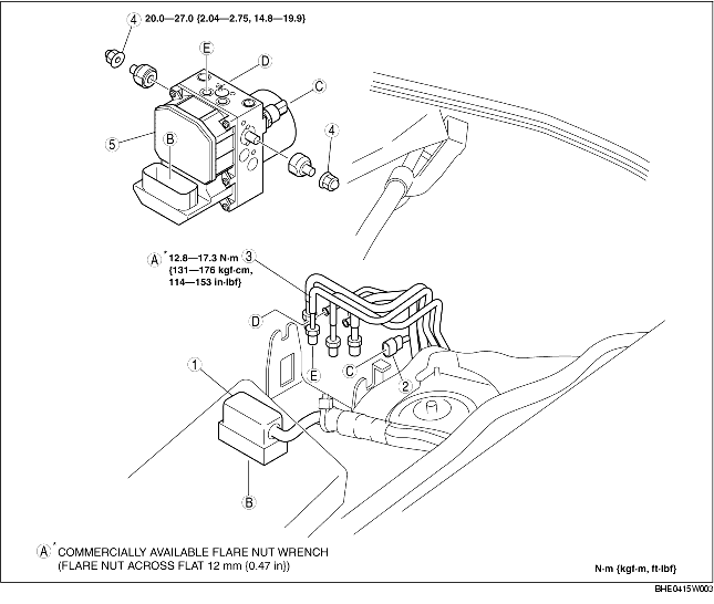
3. Remove in the order indicated in the table.
4. Install in the reverse order of removal.
|
1
|
Connector
(See Connector Removal Note.)
(See Connector Installation Note.)
|
|
2
|
Brake fluid pressure sensor connector
|
|
3
|
Brake pipe
(See Brake Pipe Removal Note.)
(See Brake Pipe Installation Note.)
|
|
4
|
Nut
|
|
5
|
DSC HU/CM
|
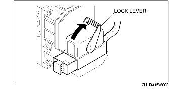
1. Rotate the lock lever in the direction of the arrow, and remove the DSC HU/CM connector.
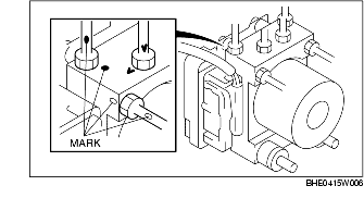
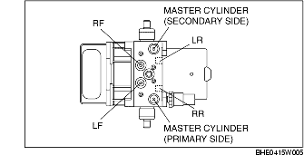
1. Mark the brake pipe connecting positions before removal for reference during installation.
1. When removing/installing the DSC HU/CM from/to the vehicle, attach a strip of protective tape on the DSC HU/CM connector to prevent brake fluid from entering.
1. When installing the brake pipe, align the marks made before removal with the DSC HU/CM as shown in the figure.
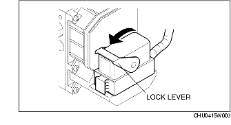
1. After connecting the connector, rotate the lock lever in the direction of the arrow to install the DSC HU/CM connector.