1. Remove the following parts:
2. Drain the engine coolant. (SeeENGINE COOLANT REPLACEMENT.)
3. Disconnect the brake vacuum hose.
4. Disconnect the quick release connector going to the charcoal canister from the engine room side. (See QUICK RELEASE CONNECTOR REMOVAL/INSTALLATION.)
5. Disconnect the plastic fuel hose. (See BEFORE REPAIR PROCEDURE.) (See FUEL INJECTOR REMOVAL/INSTALLATION.)
6. Remove the ignition coil. (See IGNITION COIL REMOVAL/INSTALLATION.)
7. Remove the A/C belt. (See DRIVE BELT REPLACEMENT.)
8. Remove the A/C compressor with the pipes connected and secure the A/C compressor using wire or rope so that it is out of the way.
9. Disconnect the engine wiring harness from the main fuse block side.
10. Remove the engine under cover.
11. Disconnect front ABS wheel speed sensor connector. (See FRONT ABS WHEEL-SPEED SENSOR REMOVAL/INSTALLATION.)
12. Disconnect the radiator hose, the heater hose and coolant reserve tank hose.
13. Remove the clutch release cylinder with the pipes connected and secure the clutch release cylinder using wire or rope so that it is out of the way. (MT) (See CLUTCH RELEASE CYLINDER REMOVAL/INSTALLATION.)
14. Remove the shift lever component . (MT) (See TRANSMISSION REMOVAL/INSTALLATION [R15M-D].) (See TRANSMISSION REMOVAL/INSTALLATION [Y16M-D].)
15. Disconnect the selector link. (AT) (See AUTOMATIC TRANSMISSION REMOVAL/INSTALLATION.)
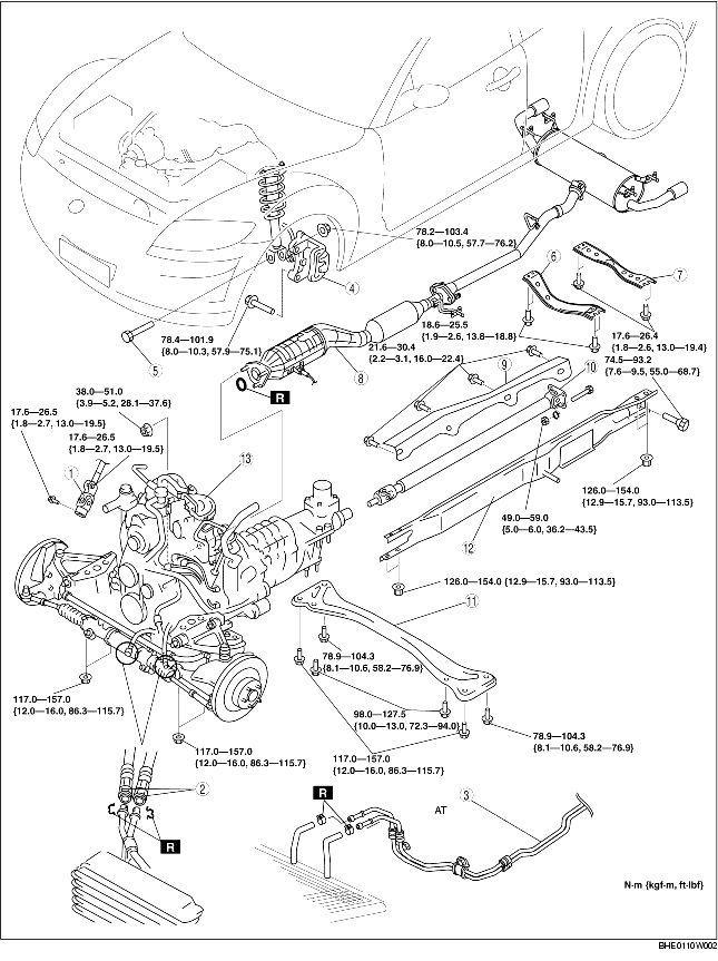
16. Remove the engine, transmission, and crossmember component using an engine lifter in the order indicated in the table.
|
1
|
Universal joint
|
|
2
|
Oil hose
(See Oil Hose Removal Note.)
(See Oil Hose Installation Note.)
|
|
3
|
AT oil cooler hose (AT)
|
|
4
|
Calliper component
|
|
5
|
Front strut lower bolt
|
|
6
|
Front tunnel member
|
|
7
|
Rear tunnel member
|
|
8
|
Catalytic converter, middle pipe, main silencer
|
|
9
|
Heat insulator
|
|
10
|
Propeller shaft
|
|
11
|
Transverse member
|
|
12
|
Power plant frame
|
|
13
|
Engine, transmission, crossmember component
|
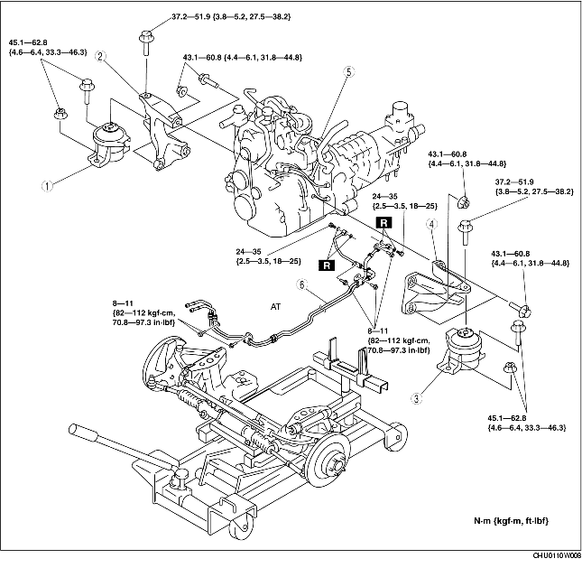
17. Remove the engine and transmission from the crossmember component lifter in the order indicated in the table by suspending them with a crane.
|
1
|
Engine mount rubber (RH)
|
|
2
|
Engine mount bracket (RH)
|
|
3
|
Engine mount rubber (LH)
|
|
4
|
Engine mount bracket (LH)
|
|
5
|
Engine, transaxle
|
|
6
|
AT oil cooler pipe
|
18. Install in the reverse order of removal.
19. Start the engine and inspect and adjust the following:
20. Perform the on-road test and verify that there is no vibration or noise.
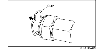
1. Remove the clip as shown in the figure and disconnect the oil pipe.
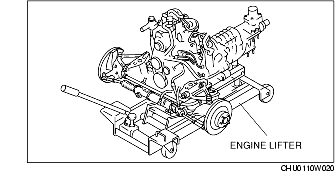
1. Secure the engine, transmission, and crossmember component using an engine lifter.
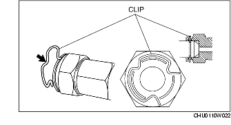
1. Connect a new clip as shown in the figure and connect the oil hose.