|
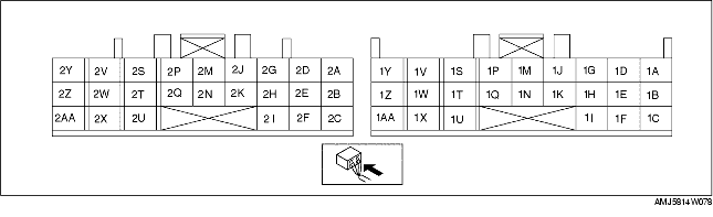
Terminal
|
Signal
|
Connected to
|
Test Condition
|
Voltage (V)
|
Action
|
|---|---|---|---|---|---|
|
1A
|
Battery back up supply
|
Battery
|
Constant
|
B+
|
• Inspect related harness
|
|
1B
|
-
|
-
|
-
|
-
|
-
|
|
1C
|
-
|
-
|
-
|
-
|
-
|
|
1D
|
TR switch
(P position)
|
TR switch
|
P position
|
Below 1.0
|
• Inspect TR switch
• Inspect related harness
|
|
Other positions, all ranges
|
B+
|
||||
|
1E
|
M range switch
|
M range switch
|
M range
|
Below 1.0
|
• Inspect Selector lever component
• Inspect related harness
|
|
Other positions, all ranges
|
B+
|
||||
|
1F
|
-
|
-
|
-
|
-
|
-
|
|
1G
|
Brake switch
|
Brake switch
|
Brake pedal depressed
|
B+
|
• Inspect Brake switch
(See BRAKE SWITCH INSPECTION)
• Inspect related harness
|
|
Brake pedal released
|
Below 1.0
|
||||
|
1H
|
-
|
-
|
-
|
-
|
-
|
|
1I
|
-
|
-
|
-
|
-
|
-
|
|
1J
|
-
|
-
|
-
|
-
|
-
|
|
1K
|
-
|
-
|
-
|
-
|
-
|
|
1M
|
-
|
-
|
-
|
-
|
-
|
|
1N
|
-
|
-
|
-
|
-
|
-
|
|
1P
|
-
|
-
|
-
|
-
|
-
|
|
1Q
|
-
|
-
|
-
|
-
|
-
|
|
1S
|
-
|
-
|
-
|
-
|
-
|
|
1T
|
-
|
-
|
-
|
-
|
-
|
|
1U
|
-
|
-
|
-
|
-
|
-
|
|
1V
|
CAN_H
|
PCM
|
Because this terminal is for serial communication, good/no good judgment by terminal voltage is not possible. Carry out inspection according to DTCs.
|
-
|
• Inspect related harness
|
|
1W
|
Shift up/Shift down signal
(Steering shift switch)
|
Steering shift switch
|
Up switch operated
(Steering shift switch)
|
2.0
|
• Inspect steering shift switch
• Inspect related harness
|
|
Down switch operated
(Steering shift switch)
|
2.5
|
||||
|
Others
|
4.0
|
||||
|
1Y
|
CAN_L
|
PCM
|
Because this terminal is for serial communication, good/no good judgment by terminal voltage is not possible. Carry out inspection according to DTCs.
|
-
|
• Inspect related harness
|
|
2A
|
Oil pressure switch B
|
Oil pressure switch B
|
2GR or 4GR
|
Below 1.0
|
• Inspect oil pressure switch B
• Inspect related harness
|
|
Others
|
Above 10
|
||||
|
2B
|
TR switch
(N position)
|
TR switch
|
N position
|
B+
|
• Inspect TR switch
• Inspect related harness
|
|
Other positions, all ranges
|
Below 1.0
|
||||
|
2C
|
TR switch
(R position)
|
TR switch
|
R position
|
Below 1.0
|
• Inspect TR switch
• Inspect related harness
|
|
Other ranges, all positions
|
B+
|
||||
|
2D
|
Down switch
(Selector lever component)
|
Down switch
(Selector lever component)
|
Shift down
(M range)
|
Below 1.0
|
• Inspect Selector lever component
• Inspect related harness
|
|
Other ranges, all positions
|
B+
|
||||
|
2E
|
TR switch
(D range)
|
TR switch
|
D range
|
Below 1.0
|
• Inspect TR switch
• Inspect related harness
|
|
Other ranges, all positions
|
B+
|
||||
|
2F
|
Oil pressure switch C
|
Oil pressure switch C
|
3GR or 4GR
|
Below 1.0
|
• Inspect oil pressure switch C
• Inspect related harness
|
|
Others
|
Above 10
|
||||
|
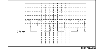
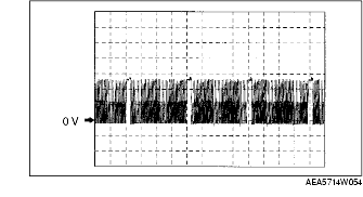
2G
|
Turbine sensor
|
Turbine sensor
|
• Inspect using the wave profile.
|
• Inspect turbine sensor
• Inspect related harness
|
|
|
2H
|
Oil pressure switch F
|
Oil pressure switch F
|
R position
|
Below 1.0
|
• Inspect oil pressure switch F
• Inspect related harness
|
|
Others
|
Above 10
|
||||
|
2I
|
Up switch
(Selector lever component)
|
Up switch
(Selector lever component)
|
Shift up
(M range)
|
Below 1.0
|
• Inspect Selector lever component
• Inspect related harness
|
|
Other ranges, all positions
|
B+
|
||||
|
2J
|
TFT sensor
|
TFT sensor
|
ATF temperature 20°C {68°F}
|
Approx. 1.55
|
• Inspect TFT sensor
• Inspect related harness
|
|
ATF temperature 40°C {104°F}
|
Approx. 1.08
|
||||
|
ATF temperature 60°C {140°F}
|
Approx. 0.7
|
||||
|
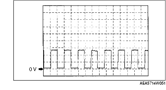
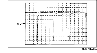
2K
|
Vehicle speed
|
VSS
|
• Inspect using the wave profile.
|
• Inspect TFT sensor
• Inspect related harness
|
|
|
2M
|
System GND
|
GND
|
Constant
|
Continuity
|
• Inspect related harness
|
|
2N
|
TFT sensor GND
|
TFT sensor
|
Constant
|
Continuity
|
• Inspect related harness
|
|
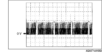
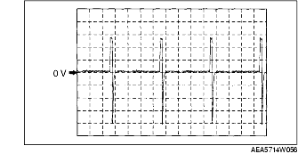
2P
|
Shift solenoid F control
|
Shift solenoid F
|
• Inspect using the wave profile.
|
• Inspect shift solenoid F
• Inspect related harness
|
|
|
2Q
|
System GND
|
GND
|
Constant
|
Continuity
|
• Inspect related harness
|
|
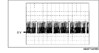
2S
|
Shift solenoid B control
|
Shift solenoid B
|
• Inspect using the wave profile.
|
• Inspect shift solenoid B
• Inspect related harness
|
|
|
2T
|
-
|
-
|
-
|
-
|
-
|
|
2U
|
GND return (solenoid ground)
|
Solenoid valve
|
Constant
|
Continuity
|
• Inspect related harness
|
|
2V
|
Shift solenoid C control
|
Shift solenoid C
|
• Inspect using the wave profile.
|
• Inspect shift solenoid C
• Inspect related harness
|
|
|
2W
|
TCC solenoid control
|
TCC solenoid
|
• Inspect using the wave profile.
|
• Inspect shift solenoid C
• Inspect related harness
|
|
|
2X
|
Pressure control solenoid control
|
Pressure control solenoid
|
N position
|
B+
|
• Inspect pressure control solenoid
• Inspect related harness
|
|
D range stall
|
Below 1.0
|
||||
|
2Y
|
Shift solenoid A control
|
Shift solenoid A
|
• Inspect using the wave profile.
|
• Inspect shift solenoid C
• Inspect related harness
|
|
|
2Z
|
Power supply
|
Main relay
|
Ignition switch ON
|
B+
|
• Inspect main relay
• Inspect related harness
|
|
Ignition switch OFF
|
Below 1.0
|
||||
|
2AA
|
Power supply
|
Main relay
|
Ignition switch ON
|
B+
|
• Inspect main relay
• Inspect related harness
|
|
Ignition switch OFF
|
Below 1.0
|
||||